Restriction Orifices
To limit a flow or regulate a pressure
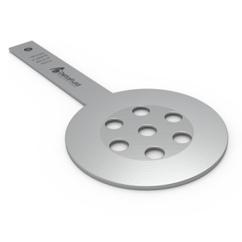
The function of a restriction orifice is a simple solution to limit a flow rate or to reduce a pressure in a pipe. It is calibrated according to the technical specifications of the installation so as to reach the desired pressure or flow rate; according to the values to be achieved, either simple restriction orifices (single-hole or multi-hole) or multi-stage restriction orifices can be proposed.
Our study takes into account the specific behaviours of your installation such as noise level, cavitation, critical regime and offers the most suitable device to avoid these phenomena. LEARN MORE (see FAQs)
It can also be concerned by the European Pressure Equipment Directive (PED 2014/68/UE).
It advantageously replaces a simple valve: simpler, more economical, more robust and maintenance free.

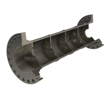
The operation of a restriction orifice is represented below:
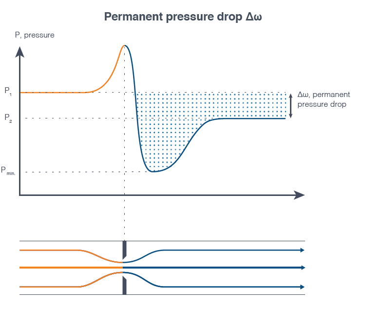
The fluid pressure decreases when going through the restriction. It reaches its minimum value shortly after the orifice (Pmin) and then increases to a stable pressure (P2). The permanent pressure loss Δω (P1 - P2) generated by the turbulences makes it possible to reduce the pressure in a pipe and / or to limit a flow.
Our expertise covers all aspects of the study of restrictions. We take into account the essential operating conditions as well as specific parameters such as noise level, cavitation (for liquids) and critical regime (sonic conditions or choked flow for gases)). LEARN MORE (FAQs)
We have developped our orifice restriction pre-selection software SIZEWELL. You can enter all the characteristics of your application, enter the main fluid parameters and validate the information on your project.
We then receive this data directly and prepare a study for you as soon as possible: Nous recevons alors directement ces données et vous préparons une étude dans les meilleurs délais : you will be able to know if your application requires a single or multi-stage restriction orifice with a simple orifice or multi-hole orifices.
Our projects managers will be able to answer all your questions particularly regarding specific parameters such as noise level, cavitation, critical flow (choked flow or choking cavitation)...
LEARN MORE on these particular phenomena
If you do not find the answer you are looking for, please contact us either by phone at +33 (0)5.59.30.85.20 or via the contact form. We will respond as soon as possible.
Cavitation in a liquid corresponds to the formation of gas bubbles due to a too low local pressure (lower than the vaporization pressure), which can happen when the pressure drops passing through the orifice. The implosion of these gas bubbles generates significant noise levels and can damage the metal elements. This is why we size the restriction orifices avoiding this phenomenon of cavitation.
If the pressure remains below the vaporization pressure downstream of the restriction, the fluid remains in gaseous form. This is the phenomenon of flashing illustrated here under.
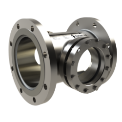
A solution to resolve this cavitation phenomenon is to propose a multi-stage restriction orifice instead of a simple restriction orifice.
TO DISCOVER
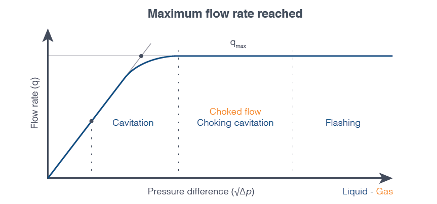
This graph represents the specific phenomena to avoid depending on the flowrate and the pressure difference.
In the vicinity of the restriction, the fluid is accelerated until it reaches its maximum speed at the restriction. As illustrated in the graph above, if the sonic velocity is reached (choked flow for a gas) or if cavitation is too important (choking cavitation for a liquid), the flow passing through this orifice does not increase even if the downstream pressure continues to fall.
Thus, we optimize the calculation of our restriction orifices while staying below the critical regime limit or choked flow (for gases) or below the cavitation limit (for liquids).
The maximum noise level depends on the operating conditions: limited to 85dB(A) by the regulatory framework for an average daily exposure in continuous operation.
Intermittent or emergency operation - higher values acceptable (see corresponding regulations).
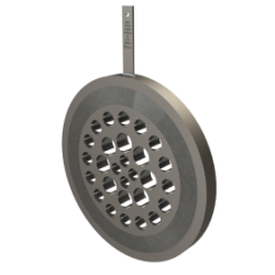
If the passage through the restriction causes a noise level beyond the standards, it is advisable to install a multi-hole restriction orifice instead of a simple restriction orifice. The number of orifices is determined by our design office according to the noise level not to be exceeded and to the starting noise level.
If the noise level is still too high, it is possible to switch to a multi-stage restriction orifice.
The thickness of the plates is calculated as a function of the generated differential pressure and the internal diameter of the piping to prevent deformation of the plate during operation.
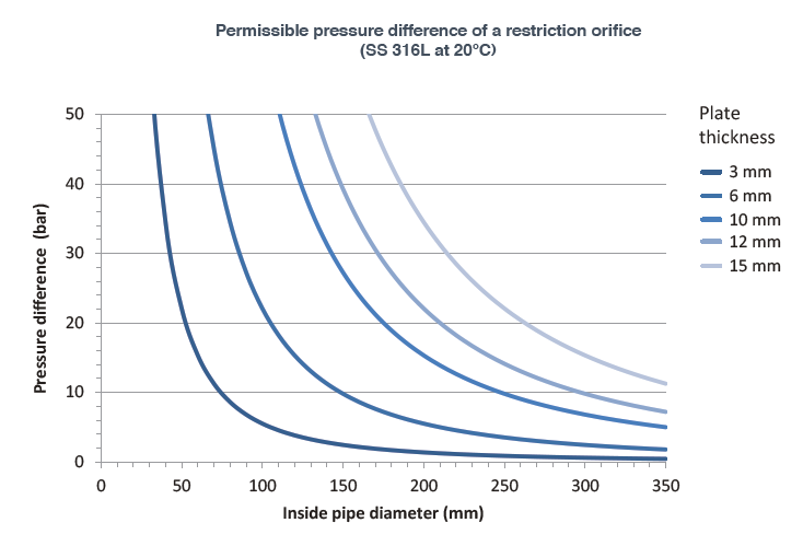
This graph indicates the minimum thickness to be respected for a 316L stainless steel plate at 20 ° C according to B31.3.