Here is the SIZEWELL online sizing tool for differential pressure flow elements.
It is an esay-to-use software: you fill in the data of your fluid and process, the software carries out preliminary calculations and directs you to the most suitable flow measurement elements. All that remains is to make your choice among all the available elements and consult the corresponding datasheets.


example display of green boxes (operation OK) sizing report
and red boxes (operation non OK) for the choice of devices
This tool also allows you to enter all the data necessary for the sizing of restriction orifices (pressure reduction & flow limitation devices). You validate your project and data is sent directly to our project managers; the calculations are carried out more quickly by our engineering office as well as the recommendations in terms of number of stages and orifices.
Important information: do not forget to save and close your project (see paragraph 10) so that we can send you a complete summary e-mail with data and pre-calculations carried out by the software (see paragraph 11).
The steps for sizing are as follows:
1 - Fill in the preliminary information & Choice of language French/English on the left on the black banner

Click on "Save"; you will receive an e-mail which will allow you to come back to the project later if you wish to consult it.
2 - Add a tag

You are invited to add the tag of your first Dp flow element.
Click on "Add a tag" to access the information to fill out.
3 - Choice of the element to size

You can now choose the element to size (box "element type selection") :
- flow measurement element (calculation sheet)
- or restriction orifice (information sheet)
Only the boxes with a red asterisk * must be completed. Others are optional.
4 - Choice of the fluid

For the choice of the fluid, a list of known fluids is pre-recorded (with all the characteristics particularly in terms of density, state - liquid or gas - and viscosity).
You must enter the first letters of the fluid IN ENGLISH (example here : water) and the fluids in the database will be displayed. Choose the fluid that concerns the tag to size. If your fluid does not appear, it is not in the database; you must then create it and enter its characteristics in the following boxes.

Here, for example, the choice of the fluid "water" of the database automatically displays the state of the fluid (liquid or steam) as well as the values of density and viscosity at base conditions.
For an unknown fluid, at least the state of the fluid (or type) and the density must be entered.
5 - Operating conditions

The operating conditions of the flow measurement element to be sized must be entered : here, operating temperature and pressure, design temperature and pressure. The units can be changed: they appear on a drop-down menu by clicking on the arrow at the end of the box.
The maximum authorized permanent pressure loss is optional: this only helps to display an alert when choosing the measurement element if this condition is not met. This parameter is not taken into account for the choice of the element if not entered at this step.

Operating conditions - tbc: including the flow rate values (mass or volume) requested here.
The density value at operating conditions is calculated automatically for a fluid known in the database.
6 - Piping values

Fill in here the parameters of your piping (choose either ISO or ASME values for the Nominal Diameter).
The drop-down menu for each box appears by clicking on the arrow at the end of the box.

By choosing the schedule in the drop-down menu, the value of the inside diameter of the pipe fills automatically (in mm). Otherwise, you can directly enter the value of the inside diameter without going through the choice of the schedule.

The value of the "upstream straight length available (in mm)" is optional. If this value is entered, the software takes it into account to validate the choice of the measurement element. And displays an alert if this value is not respected.
7 - Choice of the flow measuring element


All available flow measurement elements appear here: in green, they are suitable with the process data, in red, they are not suitable.
YOU MUST MAKE YOUR CHOICE BY CLICKING ON THE PRODUCT (here the single hole orifice plate appears circled in black like in the above left image) so that it is included in the summary sheet as explained further in paragraph 11.
When you hover over the products, additional information appears:


Example :
Left image (green box) : for the meter run, the calculated beta value is displayed as well as benefits of this product.
Right image (red box) : display of the reason which makes the product unsuitable.
8 - Choice of accessories

By clicking YES in the section "Accessories", you can choose all the accessories you need with the flow measurement element. .
By clicking NO, the display is reduced as below.
9 - Additional information

Information such as requested delivery time or any other information that you find useful will be mentioned here. You can also attach a file such as your specification or a photograph of the system to be replaced for example.
Then, click on "Save" to save all the elements entered for your first tag. The following page will be displayed:

You can here review the tag or edit it to have a look at all the data entered.
You also have the choice to "Add a (new) tag" (orange box top right) to your project. You go through all the steps already seen above for all the different tags of your project.
10 - Close the project
If the tag filled in is the only one or when you have entered all the tags of your project, YOU MUST CLOSE THE PROJECT by clicking on the corresponding box (see above, box with orange writing bottom right).
A final page is displayed for any additional comments if necessary:

You must then "Save" to finally have access to the page which details the entire list of tags for your project (here, only one tag has been entered):
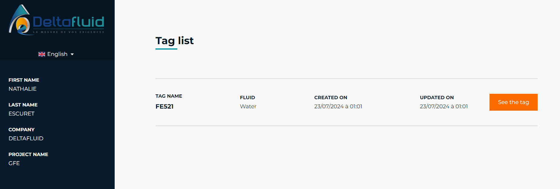
11 - Receipt of a summary e-mail

Once the project is closed, you will receive a summary email (from delta64@deltafluid.fr) with :
- the link to the project data (link "Go to project" orange box above)
- one pdf file attached by tag (here a single tag ref FE521) which includes all the data filled in and the calculations carried out by the software.
In the example below, the single hole orifice plate has been chosen (this information is displayed in blue; it is a clickable link to access the corresponding datasheet).
The data is displayed in this pdf file as well as the values calculated by the tool ("sizing results" paragraph).
The list of flow measurement elements is also displayed and indicates the elements other than the one selected which could have been suitable (green check) or not suitable (red cross). The datasheet of each element can be consulted by clicking on the blue link.
For accessories, green checkmarks correspond to those chosen and red crosses to those not chosen (here, no accessories have been selected). You can also access the corresponding datasheet by clicking on the blue link.

At this stage, you have a lot of information that allows you to pre-select the measurement element(s) suitable for your application. This is a pre-sizing.
If you wish to go further, our design office will carry out the final calculations before submitting a formal quote.